Name and location
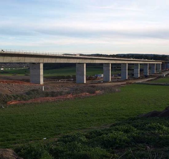
Railway viaduct over Fluvià river near the town of Bàscara (Girona, Spain)
High Speed Railway Line Madrid-Zaragoza-Barcelona-French border. Section: Pontós –Vilademuls
Key features
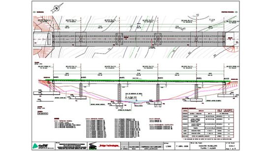
Total Length: 835m. Spans: (45m + 10x60m + 2x70m + 50m)
Average height: 19m
Use: High Speed Railway
Materials: Reinforced concrete piers and abutments and prestressed concrete deck.
Construction: Span by span with self launching gantry.
Property
Railway Infrastructure Administrator, ADIF, Spain
Construction
UTE Vilademuls: FCC CONSTRUCCIÓN + SERVIÀ CANTÓ
Years:2007-2010
BT Intervention
Construction project for the UTE Vilademuls, technical assistance and engineering construction work.
Información general

The viaduct over the Fluvià Riveris 835m in length and is the longest one in the high-speed line Madrid-Zaragoza-Barcelona-French border between Barcelona and the French border. ITcrosses over the Fluvià riverskew in the town of Bàscara, upstream of a small reservoir which increases its width to about the 100m, in an area of outstanding natural beauty and highly visible for the citizens.
The static scheme is the classical in railway bridges:
– The deck is a prestressed concrete continuous box beam, 4.00m constant depth, except in the support sections of the spans of 70m, wherethedepth is increased up to 5.5m. The deck is supported on reinforced concrete piers and abutments.
– Longitudinal fixed point, against horizontal actions, is placed on an abutment. The deck is transversally fixed to all piers by means of pot bearings.
It is noteworthy that the viaduct is located in an area of moderate seismic activity, with basic soil acceleration ab = 0.09g, this action hasbeing decisive in the design of many elements of the structure.
All foundations must be deep, with piles of 1800mm ofdiameter, both in piers and abutments
The deck has been built by the span by span method. Spans 1 and 14 are erected on falsework supported on the ground, while the openings 2-13 had been built with a self launching gantry.
At the time of execution of the works, the contractor company wanted to re-use a self launching gantry that had been used in another work but it had been designed for lower loads than the existing in this project.Bridge Technologieswas able todevelop a specific construction procedure adapted to the self launching gantry existent, which was extended to the execution of all openings except the extremes.
This construction procedure of the deck adapted to the bearing capacity of the available self launching gantry consisted of the following phases for a typical span:
– Concreting of the bottom slab, webs and the outer wings of the cross section. The weight of this partial section was supported by the self launching gantry
– Implementation of 60% of prestressing. With this percentage of prestressing was achieved that this partial section was able to supportitsself-weight and also the weight of the top slab.
– In order to avoid temporarily transverse bending local moments over the cross-section, we designed a reusable temporary bracing.
– Advancement of self launching gantry to the position for execution of next span, andconcreting the top central slab of previous span, outside the critical path
– Implementation of the remaining 40% of prestressing. The first phase of the new span was not concreted until they have totally completed the cross section of the span before. However it could be moved forward the gantry and begin the adjustment of the formwork, rebar and prestressing ducts placements works.
– All processes of bars reinforcement were standardized. The steel rods were pre-assembled at ground level in a workshop, where prestressing ducts were also positioned. The preassembled reinforcement was hoisted in sections up to the gantry with the help of an accessory structure designed for this purpose. After placing, passive bars were overlapping and the position of prestressing corrected.
The variable depth sections on piers, P11, P12 were run on falsework supported on the cap piles of his self foundations and provisionally stabilized with temporary shoring towers.
When the span had to run the 70m, thanks to having previously run the segments of variable lengths, 10 m on each side of the pier, the gantry just had to bear the weight corresponding only to 50.0m deck, so it was applied general construction procedure scheduled for the deck..
This construction procedure was perfected by A. C. Aparicio and T. Polo in 2002 for MECANOTUBO, with a detailed study by FEM of the stress state of the cross section evolution (during construction and after redistribution by creep) and details of loops and other important details.
Publications

Ingeniería de construcción del viaducto para alta velocidad sobre el río fluvià
See publication


